At 1651 on 19 July 2021, the second and third carriages parted on a KiwiRail-operated Auckland to Hamilton southbound Te Huia passenger train travelling at 91 kilometres per hour. The parting occurred at about 636.9 kilometres (see Site Information paragraph 2.76) between Papakura and Pukekohe on the North Island Main Trunk (NIMT), and caused the brakes to automatically apply in both train portions as air hoses between the carriages separated. There were no injuries, but some damage to inter-carriage electrical jumper cables.
Executive summary Tuhinga whakarāpopoto


What happened
- At 1651 on 19 July 2021, the second and third carriages parted on a KiwiRail-operated Auckland to Hamilton southbound Te Huia passenger train travelling at 91 kilometres per hour. The parting occurred at about 636.9 kilometres (see Site Information paragraph 2.76) between Papakura and Pukekohe on the North Island Main Trunk (NIMT), and caused the brakes to automatically apply in both train portions as air hoses between the carriages separated. There were no injuries, but some damage to inter-carriage electrical jumper cables.
- The two parted train portions were then recoupled by the train crew, and the train was authorised by train control to continue under a 20 kilometre per hour speed restriction to Pukekohe Station where passengers were disembarked. It is virtually certain that the park brakes on the front two of the train’s four carriages remained engaged during this journey of about 7.5 kilometres.
- After examination by mechanical staff at Pukekohe, the train continued to Hamilton under an authorised 55 kilometre per hour speed restriction and suffered a second parting, again between its second and third carriages, at about 567.4 kilometres on the NIMT.
Why it happened
- It is virtually certain that the knuckle of the newly fitted coupler at the rear of the second carriage opened due to creep, a phenomenon in automatic knuckle couplers where vibration during running can cause a coupler’s lock to move upwards and the coupler to become unlocked.
- The incident coupler’s anti-creep mechanism, which would normally limit lock creep below the point of unlocking, was ineffective due to out-of-tolerance tooling used in the casting of its lock. Quality checks performed by the coupler’s United States manufacturer, Amsted, were insufficient to detect this issue at either component or assembly level.
- Functional testing of anti-creep was relatively new to KiwiRail and was not included as part of the commissioning process when Amsted couplers were fitted to Te Huia carriages. This inexperience also meant that similar couplers fitted to KiwiRail’s freight wagons, found to be failing functional tests, were not identified as having an ineffective anti-creep mechanism.
- Park brakes were applied as part of the rectification by the train crew carrying out post-recoupling brake tests. The park brakes were not then released, likely due to severed inter-carriage jumper cables causing the trainline control circuit for the park brake release to be inoperable.
What we can learn
- Infrequent sampling after the production of parts allows for larger numbers of defective parts to be produced before defects are detected.
- Staff responding to train failures require an accurate knowledge of, and training in, key train systems.
Who may benefit
- Railway coupling system manufacturers, rail vehicle maintainers and railway operators may all benefit from the findings and recommendations in this report.
Factual information Pārongo pono
Narrative
- At 1546 (times in this report are New Zealand Standard Time (Coordinated Universal Time +12 hours) and are expressed in the 24-hour mode. Where exact seconds are used the times were taken from the train’s on board data recorder) on Monday 19 July 2021, KiwiRail passenger train service 101 (named Te Huia), left Westfield maintenance depot and travelled to Papakura Station, about 28 kilometres south of Auckland, for its scheduled Papakura-Hamilton journey. The train was made up of a DFB-type diesel electric locomotive hauling four carriages and was crewed by a train driver, a train manager and a train attendant.
- The train arrived at Papakura Station at 1620. Passengers waiting on the platform at Papakura then began to board the train. The train attendant began serving passengers from the on board café in the third carriage (carriages in this report are numbered from front-most (first carriage nearest the locomotive) to rear-most (fourth carriage)).
- The location of the café in the third carriage meant that throughout the journey passengers were walking through the train to visit it and return to their seats.
- The train departed Papakura Station at 1642:57, per its schedule, and travelled south on the North Island Main Trunk (NIMT) with 56 passengers on board.
- At 1646:48, two passengers passed from the third carriage to the second carriage via the gangway (the inter-carriage walking surface provided between adjoining passenger carriages).
- The locomotive was in power notch three (power control for locomotives in New Zealand is typically separated into eight notches, where notch one is minimum power and notch eight is maximum power. The train driver selects power notches by operating a handle in the locomotive cab) of the eight available, and the train was travelling at 91 kilometres per hour when, at 1651:27, CCTV footage from the third carriage’s leading vestibule showed initial signs of separation between the second and third carriages.
- At 1651:31, at least four seconds after the initial signs of separation, there was a sudden drop in brake pipe pressure as brake hoses between the second and third carriages were pulled apart.
- The train’s brakes applied automatically in both portions of the now parted train immediately as each vehicle responded to the drop in brake pipe pressure.
- The train driver reacted appropriately to the loss of air pressure that initiated the brakes being applied, by initially releasing the locomotive’s brakes and then allowing them to reapply. This extended the braking distance for the locomotive and the first and second carriages (the front portion).
- At 1649:40, the train manager crossed the gangway from the third carriage to the second carriage on their way to the front of the train.
- The third and fourth carriages (the rear portion) came to rest at 1651:58, 27 seconds after the brakes began to apply.
- The front portion of the train came to rest at 1652:08, 37 seconds after initial braking, and during this time it covered a distance of about 565 metres.
- GPS data from the locomotive’s Tranzlog indicated the separation distance between the front and rear portions was around 200 metres by the time both had come to rest. Figure 3 shows the recorded position of the locomotive when it came to a stop and then when the two train portions were later recoupled.

- The train monitoring system (TMS) display in the locomotive cab indicated passenger emergency brake and smoke/fire alarms. The train driver stated in their interview that they initially interpreted this alarm as likely indicating a passenger had operated an emergency brake button in one of the carriages. The train driver contacted the train manager by radio, and they began checking through the carriages to investigate the cause of the train brake application.
- Shortly after, the train driver looked backwards from their position in the locomotive cab and saw the rear portion of the train a distance backwards along the track. Immediately recognising the train had parted, they then contacted train control (the national train control centre housed in Wellington Railway Station where train movements and track occupations are authorised by train controllers) by radio to advise them of the situation and to request that northbound trains on the NIMT up main (in areas of double-tracking, separate rail tracks are often denoted by the direction of rail traffic they carry. For the NIMT, the up main carries northbound rail traffic and is positioned on the western side of the rail line, and the down main carries southbound rail traffic and is positioned on the eastern side of the rail line) be stopped as a precaution.
- Meanwhile the train attendant moved to the front of the third carriage and saw the train had parted. They immediately closed the carriage-end door and returned to the on-board café to call the train manager by mobile phone.
- The train manager arrived at the rear of the second carriage at 1655:43 and saw that the train had parted. They immediately phoned the train attendant to confirm that all passengers in the rear portion were safe.
- Permission from train control was requested and given for the train manager to go down to track level. They then walked along the track towards the rear portion, stopping part-way and taking the photographs presented as figure 4. Both photographs were taken from the same standing position, two seconds apart.

- During their walk the train manager found the 27-pin 74VDC inter-carriage jumper cable that had been between the second and third carriages and took it to the rear portion.
- The train driver began reversing the locomotive at 1712:28, bringing the front portion back towards the rear portion by around 40 metres. They then left the locomotive cab and went to track level to meet the train manager, who had returned to the front portion.
- At 1716:09, the train manager took a photograph of the second carriage’s rear end, presented as figure 5, showing its coupler knuckle in the open position. It also shows the damaged 24VDC and 400VAC jumpers that are permanently affixed to the carriage and the socket receptacle for the 74VDC jumper.

- The train driver returned to the locomotive and resumed reversing the front portion back to the rear portion’s position. The train manager meanwhile walked back to the rear portion.
- At 1719:50, the train manager took a photo of the third carriage’s front end, presented as figure 6 and showing its coupler knuckle in the closed position. This also shows a portion of the damaged 400VAC jumper.

- At 1721:24, the two train portions were mechanically recoupled by reversing the front portion into the rear portion, with the train manager assisting the train driver to pilot (guiding of a rail movement by a second person not in control of vehicle(s), generally performed when reversing) the train movement.
- A ‘pull test’ was performed to confirm proper mechanical coupling. This involved powering the locomotive forwards while the third and fourth carriages’ brakes were still applied.
- Air hoses between carriages were then reconnected and a brake test performed. This entailed the train driver applying and releasing the train brake twice, while the train manager observed brake blocks moving onto and off the wheel tread at the fourth carriage.
- The two train portions were not reconnected electrically (74VDC, 24VDC or 400VAC systems) due to inter-carriage jumper cables being damaged during the train parting.
- The train manager boarded the fourth carriage and, together with the train attendant, moved all passengers to the train’s front two carriages.
- At 1802:52, over an hour after the parting occurred, the train resumed travelling southbound at a limit of 20 kilometres per hour. The reduced speed was imposed by train control as a safety measure.
- The train reached Pukekohe at 1829:40, where it was met by other KiwiRail staff members responding to the incident.
- All passengers were disembarked from the train and provided onwards transportation to Hamilton, by either bus or the following Te Huia service, Train 103. The train attendant also left Pukekohe Station on board Train 103 at around 1900.
- KiwiRail’s site leader for Te Rapa maintenance depot (the mechanical manager) and one of their staff members (the mechanical technician) had been alerted to the incident and travelled from Hamilton by road to meet the train at Pukekohe Station. They arrived shortly after the train itself and did the following:
- confirmed the incident coupler with the train manager and inspected it, finding it to be in its closed and locked state
- confirmed the air hoses between the second and third carriages were correctly recoupled and their cocks were in their open positions
- used cable ties to restrain the 400VAC and 24VDC jumpers on the second carriage in a position where they would not trail along the ground
- unplugged the remaining section of 400VAC jumper from the third carriage and placed it on board the train
- checked other couplers throughout the train and confirmed they were closed and locked.
- The mechanical technician then tested the brakes with the assistance of the train driver. The mechanical technician walked both sides of the train during this test and confirmed brakes at each wheel responded properly to train brake commands.
- At 1939:00, the train departed from Pukekohe Station, continuing southbound to Hamilton under a 55 kilometre per hour speed restriction authorised by mechanical staff and train control, and with the train manager and the mechanical manager on board the first carriage.
- At 2050:38, as it entered Taupiri in power notch two and travelling at 45 kilometres per hour, the train again parted between the second and third carriages.
- The train driver released the locomotive’s independent brake again, with the front portion travelling about 180 metres before coming to rest. The two train portions were separated by about 95 metres once both had come to rest. Figure 7 shows the position of the locomotive when it initially came to a stop and then when the two train portions were later recoupled.

- The mechanical manager left the front portion and went down to track level to inspect the train. They took photographs of the second carriage’s coupler in its open position and the third carriage’s coupler in its closed position, presented as figure 8 and figure 9.


- The mechanical manager and train manager assisted with recoupling the train and testing brakes. At 2107:30, the train resumed travelling, arriving at Te Rapa depot in Hamilton at 2142:55 without further incident.
Personnel information
Train driver
- The train driver had 46 years’ experience in railways, with 41 years of this in train driving. They had experience in freight and passenger operation.
- The train driver had previous experience of train partings occurring for freight services, but had not been involved in a passenger train parting until this incident.
Train manager
- The train manager had worked on the Te Huia service since its introduction in April 2021 and was certified as a train manager in June of that year.
Mechanical manager
- The mechanical manager had 10 years’ experience with KiwiRail in rolling stock maintenance roles, and before this a background as an automotive technician.
Mechanical technician
- The mechanical technician had two-and-a-half years’ experience with KiwiRail, including one year as a team leader. Their previous background was in commercial road vehicle maintenance.
Train/vehicle information
Te Huia
- Te Huia is the Hamilton-Auckland passenger service that began running on 6 April 2021. It is operated by KiwiRail on behalf of the Waikato Regional Council.
- At the time of the incident Te Huia weekday services included two return trains from Hamilton’s Frankton Station to Papakura Station, morning and evening.
- Te Huia trains are made up of SR, SRC and SRV class carriages (collectively referred to as SRx class in this report), hauled by DFB class locomotives especially adapted for SRx carriage control.
SRx class carriages
- The SRx class were originally British Rail Mark 2 carriages, built in the United Kingdom (UK) during the 1970s. They were imported to New Zealand after being removed from UK services and re-engineered to suit New Zealand’s rail conditions.
- Before their conversion to SRx class, they were SA/SD class carriages used in push-pull (train operation where a driving trailer car, fitted with cab controls, is remotely connected to a locomotive at the opposing train. Allows the train to be driven from the locomotive end (‘pull’ operation) or the driving trailer end (‘push’ operation)) commuter train services for the Auckland rail network. They were withdrawn from this service in 2015, being replaced by the AM class electric multiple units when Auckland’s rail network was electrified.
- Subsequent to being withdrawn from service the SA/SD class carriages underwent a conversion to SRx class. This involved extensive refurbishment, upgrade and interior refitting by KiwiRail at their Hutt Valley workshops. Three different SRx carriage sub-classes were created.
Automatic knuckle couplers
- Couplers are used to mechanically connect rail vehicles in a train. Several types of railway coupler exist, with automatic knuckle couplers being a common type used in New Zealand and overseas.
- Automatic knuckle couplers feature a pivoting knuckle that has an open and closed position. A lock is used to hold the knuckle in its closed position and works by dropping into a pocket between the knuckle’s tail and the coupler body casting. A release mechanism allows the lock to be manually lifted into its unlocked position.
- To couple two rail vehicles one or both automatic knuckle couplers must be in the unlock position, and then the one vehicle is moved into the other. This coupling force closes the knuckles and gravity acts to drop the lock(s) into the locked position. No manual action by persons between rail vehicles is required to complete mechanical coupling (hence ‘automatic’), although train crew are required to check the coupling is complete. Figure 10 shows coupling with one or both knuckles open.

Buckeye drophead couplers
- Buckeye drophead was the coupler type fitted to British Rail Mark 2 carriages since they were imported from the UK. ‘Buckeye’ is the name of the Ohio foundry that supplied these couplers, and ‘drophead’ refers to its ability to manually move the automatic knuckle head downwards. Buckeye drophead couplers have been operated exclusively in their automatic knuckle coupler position while in New Zealand service.
Amsted A-P rotary bottom operation coupler
- KiwiRail sourced new couplers for the SRx carriages from Amsted. The couplers were Amsted’s A P type with rotary bottom operation, shown in figure 11.
- Rotary bottom operation refers to the release mechanism being located below the coupling head designed to accommodate a rotating lever operated from the side of the rail vehicle.

- KiwiRail procured four A-P couplers for trial before wider fitment to the SRx fleet. Three were fitted to the incident train and the fourth was retained as a spare. Fitting of the trial couplers was completed a week before the parting incidents.
- This comprised of fitting both ends of SR5801 and the No. 2 end (rail vehicle ends are typically denoted as No. 1 end and No. 2 end in New Zealand (and commonly elsewhere). SRx carriages can travel in either direction, but must be coupled No. 1 to No. 2 end. For the incident train all carriages were travelling with No. 1 end leading) of SR3285 with A-P couplers and the No. 1 end of SR3285 with a Buckeye drophead coupler, so that both ‘A-P to A-P’ and ‘A-P to Buckeye drophead’ coupling combinations could be trialled (see figure 15).
- A release lever was fitted for the A-P coupler at the No. 1 end of SR5801, as shown in figure 12.

- Release levers, however, could not be fitted to No. 2 ends due to space constraints caused by inter-carriage air cocks and hoses on the B-side (rail vehicle sides are typically denoted as A-side and B-side. When looking towards the No. 1 end from inside an SRx carriage interior, the A-side is on the right and the B-side is on the left) of SRx carriages, as shown in Figure 13.

- Figure 14 summarises the coupler configurations of interest to this inquiry, and their positions throughout the incident train.

Anti-creep protection
- Anti-creep protection is a feature built into automatic couplers that prevents the lock from working upwards (or ‘creeping’) into its unlocked position by vehicle-borne accelerations. In the absence of other forces gravity will generally keep the lock in its locked position (ie, fully down), but the squeezing force exerted on the lock by the knuckle when the coupler is under draft loading (describes when a coupler is in a tensile condition, or carriages are pulling away from each other. Contrasts with buff loading, which is the compression condition when carriages are pushing into one another) can maintain the lock’s vertical position and contribute to upwards creep.
- Automatic knuckle couplers can feature multiple levels of anti-creep protection (primary, secondary, etc). For the Amsted A-P coupler the design features only primary anti-creep protection.
- The primary anti-creep protection for the Amsted A-P coupler works by a slotted hole in the lock’s tail where the locklift toggle mates with it and an anti-creep lug in the coupler body cavity. When the locklift toggle is acted upon independently of the lock, as is the case during intentional manual uncoupling, the locklift toggle slides in the lock tail’s slotted hole and creates clearance between the upper edge of the locklift toggle and the anti-creep lug. Once this is cleared the locklift toggle continues lifting the lock upwards to its unlocked position, as shown in Figure 15.

- If an upward force acts only upon the lock, or the lock and the locklift toggle simultaneously, the toggle will remain at the lower end of the lock’s slotted hole. In this position, the locklift toggle’s upper edge cannot clear the anti-creep lug in the coupler body, so both the toggle and the lock are prevented from moving upwards beyond this limit. Figure 16 shows this mechanism and the maximum limit of upwards creep for the lock.

- Anti-creep protection can be functionally tested by applying two pry bars in the positions shown in figure 17 and confirming that the lock cannot be pried upwards into its unlocked position.

- KiwiRail introduced anti-creep testing as part of routine preventative maintenance for automatic knuckle couplers in October 2019.
Spring-applied park brakes
- Park brakes are used to secure rail vehicles against rolling when left unattended. Manually applied park brakes, commonly referred to as handbrakes, feature a lever or hand-wheel for persons to apply and release the park brake. Spring-applied park brakes (SAPBs) instead apply brake force with a spring that is then held off by compressed air during running.
- SRx carriages use SAPBs on their second and third (ie, inner) axles. This is a combined brake cylinder unit that also features a service brake portion. The outer axles are fitted with brake cylinder units that perform service braking only. Figure 18 shows these two brake cylinder unit types.

- Electro-Pneumatic (EP) valves on each carriage allow for park brakes to be applied and released by push-buttons (‘PB APPLY’ and ‘PB RELEASE’, respectively) inside the locomotive cab, as shown in figure 19.

- The EP valves are bi-stable, meaning they will remain in their last-commanded state of either apply or release until they receive a command to the alternate state. A pressure switch in each carriage returns a continuous signal when park brakes are applied, which controls the ‘PB APPLY’ push-button’s lamp. The ‘PB RELEASE’ push-button is not fitted with a lamp.
- The underfloor cabinet that houses the EP valve on each carriage has a ‘Rotowink’ fitted to its exterior, as shown in figure 20. Rotowinks respond to air pressure, changing colour in its presence or absence. For the SRx carriage park brake system, they are connected to the EP valve output and configured so that they display green when air pressure is present and display red when air pressure is vented.

Recorded data
Train data recorders
- Locomotive DFB7295 was fitted with a Tranzlog event recorder. Verified data for the full day was obtained by the Commission and sections of it have been used in this report where required.
- Naming of Tranzlog input signals had not been updated to reflect the modifications made to Te Huia DFB locomotives, so signal names did not reliably match the monitored circuits. This issue was eventually resolved with a signal translation document provided by KiwiRail.
- All four carriages were fitted with a CCTV system. The Commission obtained footage covering the period of the first train parting.
Other data sources
- Data from KiwiRail’s track evaluation car, EM80, was obtained for the track section where the first parting occurred. This provides locations for where track geometry or other features exceed maintenance limits. Some of this information is included in Appendix 1.
Site information
- Both train partings occurred on the NIMT’s down main. The NIMT is measured by each kilometre, referred to as ‘metrage' (metrage is marked out by trackside pegs every kilometre and every half kilometre and is used as a way of communicating the track location of features, such as culverts, train signals or track faults. Metrage is measured and read in kilometres), starting at Wellington Station (0 kilometres). The metrage increases in a northerly direction through to Britomart Transport Centre in Auckland (682 kilometres). The metrages of Pukekohe and Papakura are 628.86 kilometres and 647.02 kilometres, respectively. Paerata (633.29 kilometres) was the closest significant location to the incident.
First parting
- The location where the train began to part is estimated to have been between NIMT 636.850 kilometres and NIMT 636.950 kilometres. This estimation is based on Tranzlog data showing brake pipe pressure beginning to drop at NIMT 636.736 kilometres, CCTV footage showing the first signs of gangway separation about four seconds before this, and an average recorded speed of about 90 kilometres per hour during this period.
- Appendix 1 provides information on the track gradients and curvature in this area.
Second parting
- Tranzlog data showed brake pipe pressure beginning to drop at NIMT 567.38 kilometres between Taupiri and Huntly. No CCTV footage was able to be obtained by the Commission for this parting due to system issues related to the first parting. However, as with the first parting, the mechanical uncoupling will have slightly preceded the drop in brake pipe pressure.
- Appendix 2 provides information on the track gradients and curvature in this area.
Tests and research
Laser scanning of coupler components
- The incident coupler’s components were laser-scanned and the images were obtained by the Commission (see figure 21).

Vertical shake-table tests
- Following the incident, KiwiRail performed testing of an A-P coupler on a shake-table with the intent of recreating creep under controlled conditions. Commission investigators were present to witness this testing. The shake-table arrangement, shown in figure 22, included a turnbuckle to simulate draft loading on the coupler knuckle.

- For testing, the shake-table was sinusoidally excited (moved in a wave motion) at a frequency of 3.1 Hz. This approximated the natural frequency of SRx carriages, as advised by KiwiRail Engineering.
- The A-P coupler used for this testing was a trial coupler intended for use with AK class carriages (a class of carriage used by some scenic passenger train services within New Zealand). The trial couplers had never been fitted to any rail vehicles. The coupler body casting design differed in the design of its butt (a part of the coupler body casting. Positioned at the opposite end to the coupler head and used to connect the coupler to the vehicle (via other draw gear components) from the type used for SRx carriages, due to different vehicle-side mounting interfaces. The remainder of the coupler body and all other coupler components were of the same design.
- The results of the testing are explained in section 3.14.
Previous occurrences
- Relevant previous occurrences in New Zealand include two Commission inquiries:
- RO-2005-115: where an empty passenger train parted between the locomotive and a guard’s van, with subsequent disruption to trainline circuits in the severed jumper cable causing passenger doors to open while the train was still in motion
- RO-2013-101: where a freight train with defective brakes parted and derailed. The parting was attributed to a hook-and-pin coupler being improperly secured.
- Internationally, the following Canadian inquiries provide useful information for this incident:
- R15T1073: where unbraked wagons uncoupled and ran away within a shunting yard, leading to a collision and derailment of several vehicles. Uncoupling was found to have occurred due to the knuckle opening as a result of excessive coupler component wear
- R17V0096: where unbraked wagons uncoupled and ran away, colliding with track engineering equipment and resulting in multiple fatal and serious injuries. The coupler knuckle was found to have opened as a result of a lock being only partially engaged during coupling, due to lock dimensional factors caused by manufacturing and wear
- R18Q0046: where unbraked wagons uncoupled and ran away, derailing and colliding with a maintenance building. The coupler knuckle was found to have opened due to partial engagement of a lock, caused by corrosion build-up on internal coupler components.
- None of the above occurrences involved Amsted A-P type couplers.
Analysis Tātaritanga
Introduction
- The parting of the passenger train provided a credible possibility for passengers or crew to fall from the moving train. The following section analyses the circumstances surrounding the event to identify those factors that increased the likelihood of the event occurring or increased the severity of its outcome. It also examines any safety issues that have the potential to adversely affect future operations.
- This analysis examines two distinct topics: first, the factors that caused the train to part; and secondly, dragging brakes during the recovery of the train.
Parting of carriages
Safety Issue: A coupler component was outside the specifications required to prevent the train from parting.
Coupler knuckle opening
- For the first train parting, both the train manager and train driver recalled the coupler at the rear of the train’s front portion (No. 2 end of carriage SR5801) being found in its open position, and the coupler at the front of the train’s rear portion (No. 1 end of carriage SRC3436) in its closed position.
- Similarly, for the second parting, both the train manager and mechanical manager recalled couplers to be in the same state.
- Coupling integrity for automatic knuckle couplers relies on the lock fully lowering to its locked position during coupling. A visual check is required by the person performing coupling, and in the case of the Amsted A-P coupler design this entails checking the locklift toggle is fully down and the rotor is turned fully down. This is shown in figure 23.

- The incident coupler was put into its coupled position between its fitment to SR5801 and test-running. During the test-running phase, the coupler was scrutinised by multiple staff members among KiwiRail’s maintenance and commissioning teams. Video footage of this test-running obtained by the Commission shows the locklift toggle to very likely be in its fully down position.
- KiwiRail had no record of the second and third carriages being uncoupled since the commencement of test-running. Also, if these carriages had required uncoupling, the absence of a release lever on the incident coupler means that it was more likely that the Buckeye drophead coupler would have been opened to achieve uncoupling rather than operating the incident coupler’s rotor.
Ineffective anti-creep protection
- Post-incident inspection of the Amsted A-P coupler fitted to the No. 2 end of carriage SR5801, performed by KiwiRail engineering staff, found it to fail a functional check for anti-creep (as it is described in paragraph 2.65 and shown in figure 17). Commission investigators later repeated this testing and confirmed the result.
- KiwiRail tested the three other trial Amsted A-P couplers for SRx carriages and found them to be similarly failing. Post-incident, KiwiRail removed these couplers from carriages and replaced them with Buckeye drophead couplers.
- Amsted were also able to replicate failure of anti-creep testing with A-P couplers in their own stock.
- Amsted’s investigation found that a lack of material in the lock’s tail portion was responsible for failing anti-creep. Figure 24 shows this lack of material, comparing the incident lock to a lock that was rectified by welding and then grinding the tail area to its design dimensions.

- This lack of material in the lock tail area meant the mechanism had greater freedom to shift backwards before contacting the coupler body and could then clear the anti-creep lug. Figure 25 shows how this allowed the lock to move fully upwards into its unlocked position, despite the locklift toggle remaining at the bottom of the lock’s slot throughout.

- Commission investigators confirmed this finding by performing a functional anti-creep check on the incident coupler, as shown in figure 17. The incident coupler with the incident lock (figure 24, left) fitted was found to consistently fail the test. The incident coupler with a rectified lock (figure 24, right) fitted was found to consistently pass the test. All other coupler components in both test configurations were from the incident coupler, with only the lock being changed.
- Vertical shake-table testing, as described in paragraphs 2.82 to 2.84, using an out-of-tolerance lock similar to the incident coupler’s lock, was able to replicate creep to the point of knuckle opening in four of 12 tests as shown in the Table 1.

- Tests conducted with a rectified lock, presented in Table 2, were able to replicate creep to the anti-creep limit (refer Figure 16), but not to the point of knuckle opening.

- The vertical shake-table testing confirmed that an out-of-tolerance lock could fail under certain conditions, whereas the in-tolerance lock did not fail when subjected to the same and more rigorous conditions
- It was noted by Commission investigators that the testing involved only the A-P type coupler, and not the combination of A-P to Buckeye type couplers as was the condition present on the train at the time of the occurrence.
-
KiwiRail was asked about the significance of this and responded in part:
The testing carried out on the A-P coupler aimed to replicate the suspected mode of failure, i.e., failure of the anti-creep function due to out of tolerance lock block, which was internal to the A-P coupler. The combination of tension and vertical loads applied to the coupler replicated those experienced in service and these would not differ significantly if the opposing coupler was A-P or Buckeye type.
Coupler loading condition and creep
- Train handling and track gradients both affect coupler loading states. For locomotive-hauled trains, ascending a gradient under power stretches the train and puts couplers into a state referred to as ‘draft’. On the other hand, descending a gradient under dynamic braking bunches the train and puts couplers into a state referred to as ‘buff’. A simple analogy is the stretching (draft) and compressing (buff) required to play an accordion.
- Under real operating conditions, couplers will transition between draft and buff loading as a train negotiates undulating gradients and the train brake is applied and released. Accepted best practice for train handling is to minimise sudden transitions between these states and avoid severe run-in (draft to buff) or severe run-out (buff to draft). A common technique to maintain train stretch and avoid run-in during application of the train brake is to release the locomotive independent brake.
- The squeezing force the knuckle applies to the lock under draft loading (ie, in tension, see figure 26) is required for creep to occur. Under buff loading this squeezing force is released, and the lock drops back to its fully locked position with gravity. Creep effectively accrues during periods of draft loading and is ‘reset’ during buff loading.

- The track gradients and train handling data from Tranzlog for the lead-up period to both train partings is presented as Appendix 1 and Appendix 2. Key points from this are summarised as follows:
- no use of dynamic braking between leaving Pukekohe Station and the first parting event (about eight minutes and 34 seconds)
- a period of about three minutes and 40 seconds of powering over mainly ascending grades in the immediate lead-up to the first parting
- a period of about 45 minutes between the last use of dynamic braking and the second parting event
- a brief train brake application, with the locomotive independent brake fully released, about 24 seconds before the second parting
- From these observations it is very likely the sustained draft loading conditions necessary for unchecked creep to cause knuckle opening existed in the lead-up to both partings.
Vertical accelerations and creep
- As described in paragraph 2.61, creep also requires a coupler to experience vertical accelerations. There is a baseline level of accelerations, even on very good condition track, and it can be expected to typically have a positive correlation with vehicle speed (ie, vehicle ride is bumpier at greater speeds). Defects in track infrastructure create brief periods of greater vertical acceleration (ie, bumps).
- CCTV footage from the carriage interiors shows a distinct bump at 1649:35, or about two minutes before the first parting. This bump is very likely a result of some infrastructure feature or defect at approximately NIMT down main 369.40 kilometres. There was no evidence found that this or any other defects were outside of normal maintenance limits.
- Carriages were also found to have wheel flats when inspected at Te Rapa depot following the incident, requiring re-profiling on a wheel lathe before the incident carriages were returned to service.
- Wheel flats result from wheel-slide occurring under braking, where material from the wheel tread surface is abraded as its slides against the rail head.
- Both the train manager and train attendant recalled during their interviews that upon resuming travel after the first train parting, wheel flats could be clearly felt and heard from inside carriages and that this had not been noticeable before the parting. It is therefore very likely the resultant brake application from an initial speed of 91 kilometres per hour, triggered by the parting, caused wheels to slide and resulted in wheel flats.
- Wheel flats create a regular bump with each rotation. Figure 27 shows the vertical displacement the axle centreline undergoes as a flat spot on the wheel tread contacts the rail.

Omitted release lever
- As described in paragraph 2.59, the incident coupler had not been fitted with a release lever, due to space constraints at the No. 2 end of SRx carriages. As part of its inquiry, the Commission has investigated the possible influence this omitted release lever had on the incident coupler’s vulnerability to creep.
- In a typical arrangement the release lever is supported at one end by the rotor. During creep the rotor is pulled around its axis of rotation and initially counteracted by the release lever’s mass. At a certain point the release lever’s centre of mass reaches a position directly above the rotor’s centre of rotation (over-centre), and beyond this point the lever’s mass acts to assist the creep force. Figure 28 shows this sequence, but it should be noted that loose clearances between mating parts provides a significant degree of freedom for all involved parts.

- The release lever is also subject to broadly the same vehicle-borne vertical accelerations as the coupler. So, while the release lever’s mass does interact with lock creep, the effect is relatively low.
- The Commission found that the lack of a release lever had negligible influence on the coupler experiencing creep, and that there was no requirement for release levers to be fitted according to the manufacturer’s specifications.
Lock manufacturing defects
Safety Issue: Checks performed on coupler components and assemblies between manufacture and fitment to carriages were unable to recognise defective anti-creep protection.
- As described in paragraphs 3.11 to 3.15, a lack of material in the lock tail resulted in the incident coupler’s anti-creep mechanism being ineffective.
- The Commission found this lack of material to be a result of out-of-tolerance tooling used in the lock’s sand-casting process. This casting was performed by a sub-supplier, who Amsted had used to produce A-P coupler locks since 2014.
- Initial functional checks performed in 2014 on assembled couplers with newly-sourced locks confirmed proper anti-creep operation. However, Amsted’s investigation found that locks cast as early as 2017 were lacking material in the tail area, so concluded tooling wear in the period 2014 to 2017 caused the issue.
- Between 600 and 800 A-P couplers supplied to KiwiRail were expected to have been affected by this issue. Not all of these had been fitted to rail vehicles, and the only couplers fitted to passenger vehicles were the three fitted to the incident train.
Dimensional checks of lock
- The following sub-sections examine the existence and performance of controls in place to prevent out-of-tolerance locks being fitted to complete coupler assemblies, and those assemblies then being fitted to rail vehicles
- Production checks (ie, checks performed on each lock after it is cast), undertaken by
- Amsted’s lock sub-supplier included application of the go gauge.
- Go gauges inspect the maximum material condition of a part by checking whether the gauge and the part ‘go’ together. If a part is too big, then it will not fit the gauge and thus fails the check.
- Production checks did not inspect parts for least material condition, (ie, whether the part was too small). Instead, this was only checked for the first lock using shims in conjunction with the go gauge.
- Figure 29 shows a photo of an out-of-tolerance lock, similar to the incident lock, with the go gauge applied. Excess clearance between the gauge and the rear of the tail area is indicated.

- The sampling frequency for detailed part checks (ie, how often a production lock is taken for detailed measurement) was not sufficient to detect this issue before affecting an estimated 600 to 800 locks.
Functional checks for anti-creep
- Amsted’s post-assembly checks on completed A-P couplers did not include routine functional testing for anti-creep (ie, the test described in paragraph 2.65).
- Although A-P couplers are not an American Association of Railroads (AAR) standard coupler type, they are broadly similar, so Amsted applied the same production practices. Specifically, AAR standard couplers did not require anti-creep testing as a production inspection point.
- In October 2019, KiwiRail introduced functional anti-creep testing to its scheduled preventative maintenance programme for automatic knuckle couplers on freight and passenger vehicles. It had been included in KiwiRail’s technical manual before this, but not required to be routinely undertaken.
- In December 2019, it was reported by KiwiRail’s maintenance depots that Amsted A-P couplers fitted to freight wagons were being found to fail functional anti-creep testing. KiwiRail’s engineers notified Amsted immediately, but due to the issue affecting near-new couplers and KiwiRail’s relative inexperience in performing anti-creep testing it was deemed by Amsted to most likely be an issue with test methodology rather than with A-P couplers themselves.
- Failing anti-creep testing was added as an agenda item to a planned Amsted engineering visit for March 2020. This visit however did not go ahead, due to New Zealand border restrictions brought about by COVID-19. It remained an open issue for KiwiRail and Amsted up until the time of this incident, but was not considered urgent, due to the presumption it was an issue with test methodology.
- The Commission would have made recommendations to address these safety issues, but KiwiRail has taken safety actions to address the issues.
Park brake dragging
Safety Issue: No controls were in place to mitigate the risk of disrupted control circuits caused by severed inter-carriage jumper cables following the parting of a passenger train.
Overheated brakes
- The train manager, train attendant, mechanical manager and mechanical technician all recalled a metallic burning odour being present on the incident train, and all associated it with overheated wheels or brakes.
- The train manager and train attendant both recalled this odour first becoming apparent when the train resumed onwards travel after being recoupled. The mechanical manager and mechanical technician both recalled the odour being present from when they first arrived at Pukekohe Station and met the train.
- The mechanical technician also found wheels to be hot when inspecting the train at Pukekohe Station, observing blistering and discolouration of heat-sensitive wheel paint (paint applied to wheel plates, normally a light grey that turns to dark grey or brown when exposed to excessive temperatures (typically around 250–300°C). Used in maintenance to identify wheels that have been subject to overheat conditions).
- Excessive brake heat can be caused by:
- heavy braking from high speed, where high levels of brake effort and high train speed create short periods of intense heat generation
- brake dragging, where even moderate brake force acting against a train’s tractive effort for prolonged periods generates excessive heat.
- Braking that occurred in response to the first train parting (at about 1651) is consistent with this first type of excessive heat generation. However, this would have seen peak brake temperature occur as carriages came to rest and then a cooling-off from that time onwards.
- This cooling-off period should have allowed the heat to dissipate, and little odour should have been apparent once the train resumed movement. Nor should heat have still been apparent to the mechanical technician at Pukekohe Station around two hours after the first parting.
- It is therefore very unlikely that observed brake overheating was solely attributable to emergency braking that occurred during the first parting.
- Examination of the data recorded by the locomotive’s Tranzlog, presented in Appendix 3 and Appendix 4, showed the ‘park brake applied’ circuit to be energised throughout the train’s journey from the first parting site to Pukekohe Station. It is possible this circuit was energised by contacting a +24VDC supply in the severed inter-carriage jumper cable. However, when considered alongside the reported burning odour it is very likely due to the park brakes remaining applied in the first and second carriages as the train continued its journey.
Checks following first train parting and recoupling
- The train manager performed an intermediate brake test after recoupling the two train portions at the first parting site. This included the train brake being applied twice, while the train manager observed brakes at the fourth (rear-most) carriage. This was in accordance with KiwiRail’s documented procedures for an intermediate brake test.
- The train manager also stated that a park brake test was performed. This is an additional element to a normal intermediate brake test that is required for vehicles fitted with SAPBs. The train manager requested the train driver to push the ‘PB APPLY’ push-button and then the ’PB RELEASE’ push-button while observing a response at the fourth carriage. It is possible the train driver simply omitted to push the ‘PB RELEASE’ push-button, but more likely the circuit was disrupted by the forceful severance of the 24VDC jumper cable during the train parting, therefore rendering the push-button inoperable.
- Disruption of circuits in the 24VDC jumper is supported by Tranzlog evidence of disturbances to the passenger emergency brake circuit and its driver override circuit, presented in Appendix 3. This is very likely to have been caused by shorting wires in the severed jumper cable and exceptionally unlikely to be from normal train operation.
- The train manager recalled observing brake blocks pushing against, and retracting from, the wheel tread surface during this park brake test, and stated that they did not use the Rotowink indicators to determine park brake status (see paragraph 2.71). It is virtually certain there was no response from the fourth carriage’s brakes, due to the 24VDC jumper cable that carries this command being severed between the second and third carriages. However, it is likely that park brakes in the fourth carriage remained released after the parting, so at the conclusion of this test the train manager would have likely observed released brakes.
- The train manager did not check brake response in any carriages other than the fourth and was not required to by KiwiRail’s intermediate brake test procedures.
Precautions following a train parting
- The Commission notes that the 400VAC cables, responsible for supplying power to non-safety critical onboard equipment, were designed to fail in a safe manner if damaged. The 400VAC cables performed as designed in this incident.
- Unlike freight wagons, where parted vehicles can be fully recoupled (ie, mechanically and pneumatically), passenger carriages normally cannot be electrically recoupled following a typical parting due to jumper cables being damaged. As occurred in this incident, this cuts off control to carriages at the rear of the parting and can cause other disruptions to safety-critical train control circuits where forceful severance of jumper cables leaves exposed conductors.
-
Commission inquiry ‘RO-2005-115: Empty passenger Train 2100, train parting and improper door opening, Ranui, 1 April 2005’ identified a similar issue for door control circuits on SA/SD trainsets (a prior incarnation of SRx carriages, see paragraph 2.48) following a train parting event:
3.5. When the trainline cable severed, short circuits sent commands to open the doors on the passenger carriages as the train was stopping.
- KiwiRail operating instructions for SRx carriages included manual isolation of both park brakes and door systems, and shutting down the 400VAC generator, but provided no information specific to train partings or what actions can be taken to mitigate the risk of disrupted trainline circuits following a parting.
- No action has been taken to address this safety issue. Therefore, the Commission has made a recommendation in section 6 to address this issue.
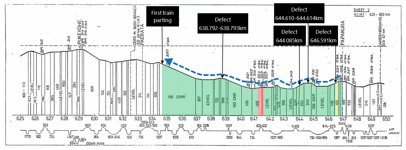
Appendix 1. Track gradient and train handling – first parting
Below is KiwiRail’s gradient and curve diagram for the section of the North Island Main Trunk where the first parting occurred. The upper portion of the diagram shows track gradient, expressed as one unit of vertical change for a denoted unit of horizontal change (eg, ‘100’ means a 1-in-100 gradient). The lower portion gives track curve radius and direction of curves.
Overlaid is the train’s progress from Papakura Station to the site of the first parting (blue arrow), and the train’s control state as recorded by the locomotive’s Tranzlog. Green denotes powering, yellow power-braking (ie, where the train brake is applied at the same time as throttle) and red when the train brake is applied.
Features of interest are identified by call-outs, including track defects, as identified by KiwiRail’s track evaluation car EM80 in December 2021.
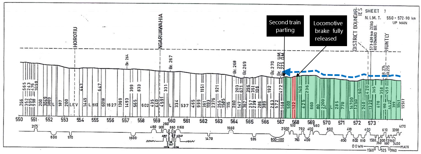
Appendix 2. Track gradient and train handling – second parting
Below is KiwiRail’s gradient and curve diagram for the section of the North Island Main Trunk where the second parting occurred. The diagram and denotations are as per Appendix 1.
Although the train brake was applied shortly before the parting, the locomotive brake was fully released during this application (as denoted by the call-out). This is a common technique to maintain stretch within a train and means the incident coupler very likely remained in draft loading.
Appendix 3. Tranzlog data – first parting and recoupling
This appendix provides plotted Tranzlog event recorder data for selected signals from the first parting to when the train resumed onwards movement towards Pukekohe Station. The first plot, A, shows the locomotive speed in kilometres per hour (as recorded by Tranzlog from the radar speed unit, no speed correction has been applied) and traction motor current in amps. The second plot, B, shows air pressures in kPa. Plots C, D and E show the behaviour of the following digital signals (raised signal indicates ON).
- O-PkBrkLT: ’park brake applied light’ return signal from connected carriages, energised when the pressure supplied to the park brake is below 460kPa (ie, pressure is insufficient to release park brakes). Controls the ‘PB APPLY’ push-button lamp in the locomotive cab, via relay. Tranzlog records this signal as ON when the input is energised.
- O-PassEMPB: ’passenger emergency brake’ signal from connected carriages, energised in normal operating conditions, but is interrupted by the operation of any passenger emergency brake button throughout all connected carriages. Tranzlog records this signal as OFF when the input is energised.
- O-LEPEB_OR: ’locomotive engineer passenger emergency brake override’ signal from a push-button inside the locomotive cab that allows the driver to override a passenger-initiated emergency brake application (intended to allow for drivers to avoid stopping in unsafe areas). Tranzlog records this signal as ON when the input is energised.
The following is an explanation of what can be inferred from this data, with reference to call-outs on features of the relevant plots.
- The parting occurs. Immediate drops in speed and motor current [A1] coincide with a rapid loss of brake pipe pressure and responding rise in brake cylinder pressure [B1]. The steady input from the passenger emergency brake circuit is lost [D1] as the inter-carriage jumper cable between the second and third carriages is severed.
- The locomotive brake valve is put into trail and then back into lead [B2], but full brake pipe pressure (550kPa) is not re-established due to disconnected hoses at the rear of the second carriage.
- Meanwhile, input from the passenger emergency brake circuit is recovered [D2]. It is not possible this represents the legitimate re-establishment of full carriage continuity (the two train portions are separated by around 200 metres), and instead is very likely the result of exposed wires in the second carriage’s severed inter-carriage jumper cable. This coincides with an input from the locomotive engineer passenger emergency brake override signal [E1], which was likely pushed before this (ie, while the train was still in motion as per the train driver’s account), but was suppressed due to likely shorting of the carriages’ +24VDC supply (wire ‘DP’). Further erratic behaviour (rapid on/off) synchronised between these two signals [D3]/[E2] is likely evidence of the severed jumper cable being disturbed by the train driver or train manager when they inspected the rear of the second carriage.
- The locomotive brake valve is put into trail [B3] and air cocks at the rear of the second carriage are closed [B4], allowing air pressure to recover (trail and brake cylinder).
- The locomotive brake valve is put into lead and brake pipe is restored to its full release pressure (550kPa) [B5].
- The train front portion rolls a short distance backwards down the track gradient [A2] as the locomotive’s independent brake is released [B6]. It is then brought to a stop by the train brake being applied [B7].
- The train front portion is moved backwards under power [A3] and the second and third carriages mechanically recoupled.
- The mechanical coupling is tested by the locomotive powering forwards [A4] against the still-applied brakes in the third and fourth carriages (a ‘pull test’ or ‘pressure test’).
- A brief dip in brake pipe pressure without a corresponding dip in equalising reservoir pressure [B8] indicates the cocks being opened and brake pipe being re-established between the two train portions.
- A brake test is performed, with the train brake being applied twice [B9]. The train manager stated during their interview that they were at the fourth carriage observing brake blocks moving on and off the wheel tread at this time.
- Between the two brake applications made as part of the brake test, the park brake applied light signal turns on [C1]. This indicates park brakes being applied in either one, or both, of the first and second carriages. Very likely this has resulted from the train driver pressing the ’PB APPLY’ push-button in the locomotive cab, as the train manager stated in their interview that they requested the train driver to apply and release park brakes as part of the brake test.
- The park brake applied light signal remains on as the recoupled train resumes onward movement to Pukekohe Station at a speed limit of 25 kilometres per hour [A5]. It is possible the train driver simply omitted to push the ‘PB RELEASE’ push-button, but more plausibly the park brake release trainline wire was disrupted (ie, shorted) at the severed inter-carriage jumper cable, so the park brakes could not be released from the locomotive cab.

Appendix 4. Tranzlog data – Pukekohe Station
Similar to Appendix 2, this appendix provides plotted Tranzlog event recorder data for selected signals from the train’s arrival into Pukekohe Station until its onwards departure. A reduced set of variables is presented, but these are otherwise, as per their Appendix 2 descriptions.
The following is an explanation of what can be inferred from this data, with reference to call-outs on features of the relevant plots.
• The train arrives into Pukekohe Station at about 18 kilometres per hour and comes to a stop [A1] as the train brake is applied [B1].
• There is a period of inactivity in the Tranzlog signals where the mechanical manager and mechanical technician arrive and inspect the train. Both stated during their interview that after inspecting the mechanical coupling between the second and third carriages that they secured the severed inter-carriage jumper cable to the second carriage with nylon cable ties.
• A brake test is performed by releasing the train brake [B2] for around five minutes. The mechanical technician stated they checked all axles across all carriages during this brake test, accounting for this sustained release period.
• The park brake applied light signal turns off [C1] shortly after the train brake is released. It is possible this occurred as a result of the driver pushing the ‘PB RELEASE’ push-button and the park brake release trainline wire having been restored in the meantime (possibly while the inter-carriage jumper was being secured). Alternatively, it may have been the result of the mechanical technician manually operating park brake EP valves on the first and second carriages. During their interview the mechanical technician stated this is the action they would have taken if they encountered applied park brakes, but could not accurately recall if they had encountered them.
• The train brake is released for a second time [B3] as part of the brake test.
• The train resumes onwards to Hamilton at a speed limit of 55 kilometres per hour [A2].
An important note for this appendix is that Tranzlog enters its sleep mode for the period denoted [B4]. In this mode analogue signals are logged at five-minute intervals (digital signals are still logged whenever a change in state occurs). The gradual sloped increase in equalising reservoir and brake pipe pressures shown in this period is likely misleading and instead, in reality, there will have been a short step increase somewhere inside this period.
